Alrighty then, everything is here, lined up and ready to install. There's going to be some big gaps in the pictures. One, because it's hard to hold onto the camera/phone and take pictures when both hands are busy putting things together, and two, because your hands bet all yucky with dirt, oil and such, the camera isn't the sort of thing you want to be messing with.
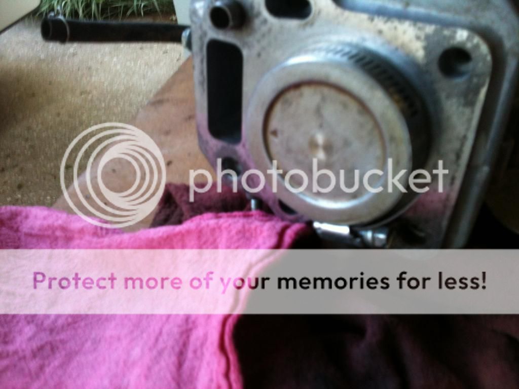
Skip forward. When I left off, the piston was to come out. The connecting rod bolts come out, the lower end of the connecting rod comes out, and you turn the crankshaft around to where the upper end of the connecting rod is lined up in a straight shot out the cylinder, and push the piston out the top end.
If you are installing new rings, you'll want to hone the cylinder. I use one of those contraptions that has the three arms that look vaguely like windshield wipers and attach it to my hand held drill. I coat the honing stones with a stuff called Engine Assembly Lube. Its a black goo that has moly-graphite in it. Again, easy does it, work it in and out of the cylinder just a few times and take a look. Again, sorry no pictures here because I tend to get really intent on what I'm doing and my focus has nothing to do with photography. You can google cylinder deglazing or cylinder honing and watch youtube videos by other folks who have done this a time or two.
Now your cylinder is deglazed, got yourself a nice cross hatch pattern and now it's time to get the piston ready with it's new rings. There are three rings to remove. Do so carefully so as not to scratch the piston all to heck. Once the old ones are out of the way, the three new rings go on. Get yourself a piston ring expanding tool. Doesn't have to be anything fancy, just one that will firmly hold the open ends of the rings and spread them just far enough to clear the piston. It's at this point that I tend to get nervous because I've done this before, gotten over zealous, and broke a ring putting it on. So, google "piston ring install" and learn from the experts. Sorry, no pictures here. Takes both hands to put these things on, and sorry, no pictures of them on because once I had them on I went into auto pilot and got ready to put the piston in.
As I said, there are three rings on the piston. Arrange the open gaps of the rings so they aren't overlapping. Imagine the face of a clock and sort of arrange the gaps at something like 10:00 - 2:00 - 6:00, or so. The manual says 120 degrees. You get the idea. I oil the outside of the piston and the inside of the cylinder generously with motor oil so things slide easily.
The rings will need to be compressed around the piston in order to get them into the cylinder. There are piston ring compressors made for this, but a hose clamp works well too, and it's cheaper.
Special note here. I've done three of these engines before, and have simply used the standard rings on each. I have been lucky that this is all that was needed on each of the engines, and hopefully this one will be the same. My local Honda dealer tells me he's never been so fortunate, and has had to have the ones he's done bored out to the next size.
Slide the piston into the cylinder until you get to the hose clamp. Remember to put the arrow on the top of the piston facing the push rod side of the block. This will position the connecting rod in the correct orientation as well. Then I use a mallet with a plastic handle on it, put the end of the handle on the top of the piston and rap the head of the mallet with the palm of my hand. Couple of raps and the piston will slid in and the hose clamp just falls away.
Turn the crankshaft around while lining the upper end of the connecting rod up. Once they're mated up with each other, put the lower end of the connecting rod in place. Remember the lines to correctly orient the upper and lower connecting rod. Reinstall the connecting rod bolts.
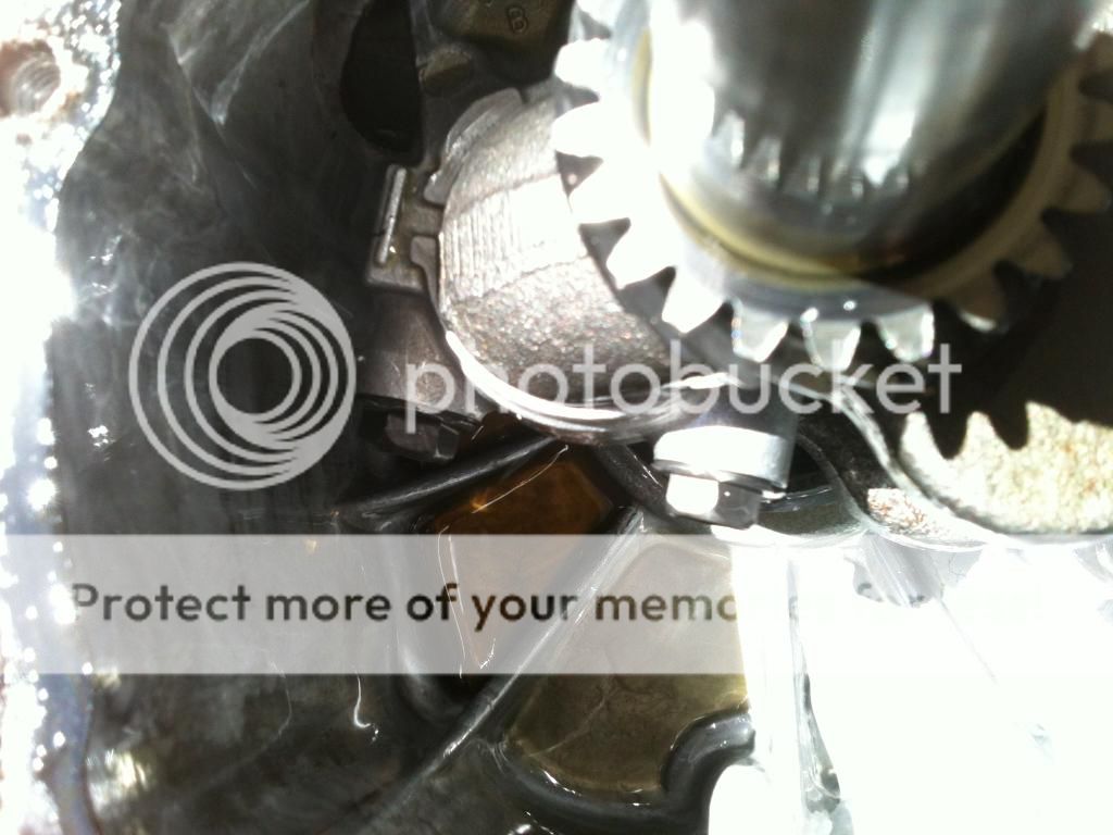
Turn the crankshaft around until you can get your torque wrench down in the crankcase. It will fit, and tighten the connecting rod bolts to 7.2 - 10.1 ft-lb.
You probably either took the valve lifters out, as the manual says to mark which one is intake and which one is exhaust so you can return them to the same spot, or they fell out as you turned the engine around. Put those back in now. Reinstall the cam shaft and line up the timing marks.

Now you're ready to put the oil pan back on. Be sure the two dowel pins are in their places on the engine block and check again that all the old oil pan gasket material has been removed from the block and oil pan. Nothing worse than getting all of this done, put the engine back on and find you have an oil leak around the gasket. Remove the oil pan gasket from the package and put it on the block. I use a high temp silicone sealant on both sides of the gasket just for good measure. Probably don't have to, but it makes me feel better. I just lightly coat the gasket and rub it smooth with my finger. The sealant also helps hold gaskets in place while you are lining parts up.
Line the oil pan up over the PTO end of the crankshaft, and drop it down into place using the dowel pins to line everything up for you. Don't force it. Sort of wiggle and jiggle it into place because you have to get the gears on the governor and drive shaft to mate up with their partners on the camshaft and crankshaft. Don't panic either, these things do seem to line up pretty easily. Lightly tap it down with the heal of your hand. Put the pan bolts back in and get your torque wrench ready again. You don't have to change the setting on your torque wrench from the one you used on the connecting rod bolts, because the torque for the pan bolts on the GXV120 is the same. 7.2 - 10.1 ft-lb. There are seven bolts, and though the manual does not specify any particular pattern to follow in tightening them, I do sort of like when putting a 5 bolt wheel back on and alternate in sort of a cross pattern when tightening them. I also sort of do it in stages, tightening them to something less than full torque specs, then go around again and tighten them to their final torque.
Now is when I put the bottom oil seal in. I've done it by putting the oil seal in the pan first, but there is a rim on the PTO that always seems to catch the inner lip of the seal and want's to turn it inside out when doing it that way. It goes on so much easier by installing it after the pan is in place. Oil up the PTO and the inside of where the seal goes, and oil up all the surfaces of the seal. Put it on over the PTO and slide it in place. It just might go in with finger pressure, but I use my handy dandy seal driver to make it easier.
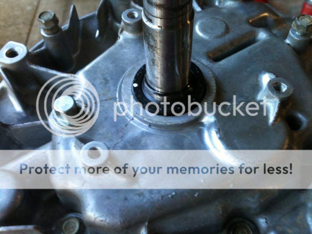
Different engine, but you get the idea here.

At this point I like to give the cranks shaft a spin just to see the piston go up and down, and to see how things "feel" so far. Everything should turn easily.
Now we're ready to turn our attention back to the top side. Put the head gasket in place. Take note of what you're doing here. It will go on the wrong way, and a quick glance makes you think all is well.
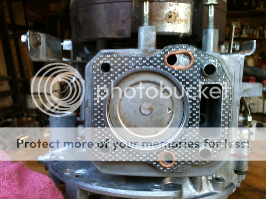
But don't be fooled into a false confidence of doing it right, like I was once, and make sure to get the holes lined up correctly.
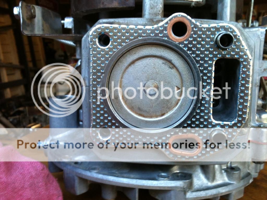
Just to let you know, the oil comes out in a really fine spray when you put it on wrong. Then you get to take the head off again and do it the right way.
Slide the cylinder head back onto the top of the engine. The two dowel pins will guide it into place and you reinstall the four bolts. There is a pattern to tightening these up. Facing the engine it's (1)upper left, (2)lower right, (3)lower left, (4)upper right. They get tightened to 15.9 - 18.8 ft-lb.
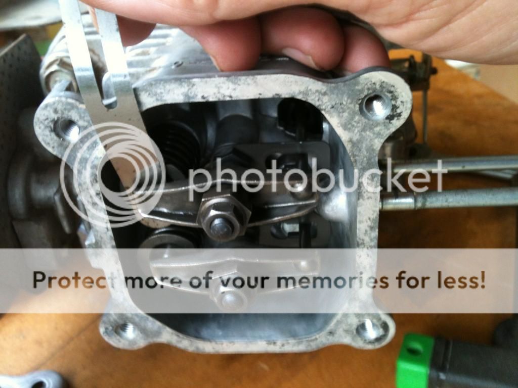
Now you can drop the push rods into place. It helps to shine a flash light down into the chamber to see the ends of the valve lifters to mate the end of the push rod into the cupped end of the lifter. The reverse the process of compressing the valve spring and turning the rocker arm up over the push rod.
Next, set the valve clearance. Turn the crankshaft until the psiton is at top dead center. Both rocker arms should wiggle, indicating the valves are closed. Get your feeler gage out and check the clearance.
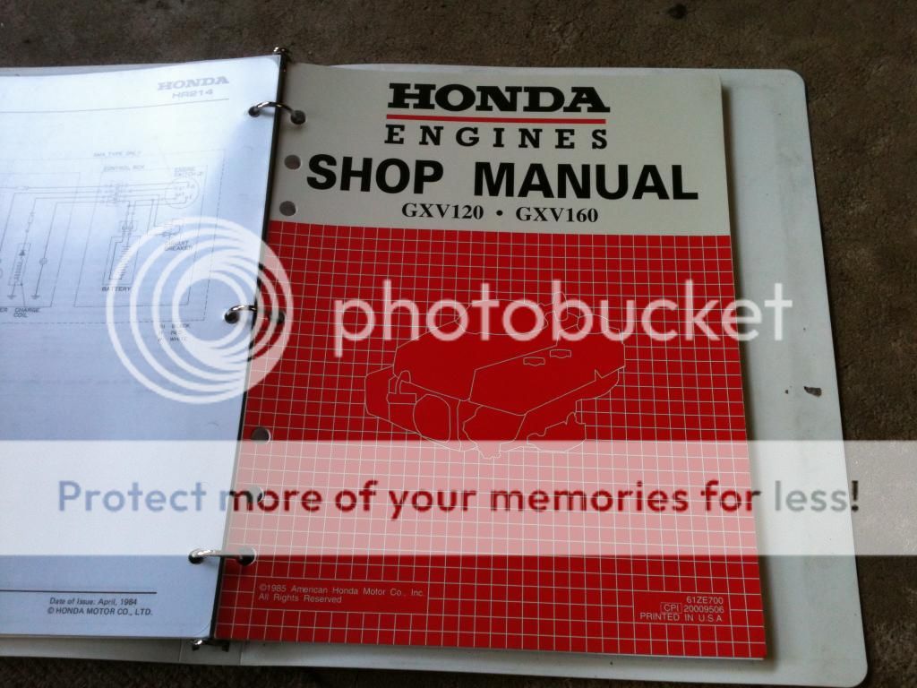
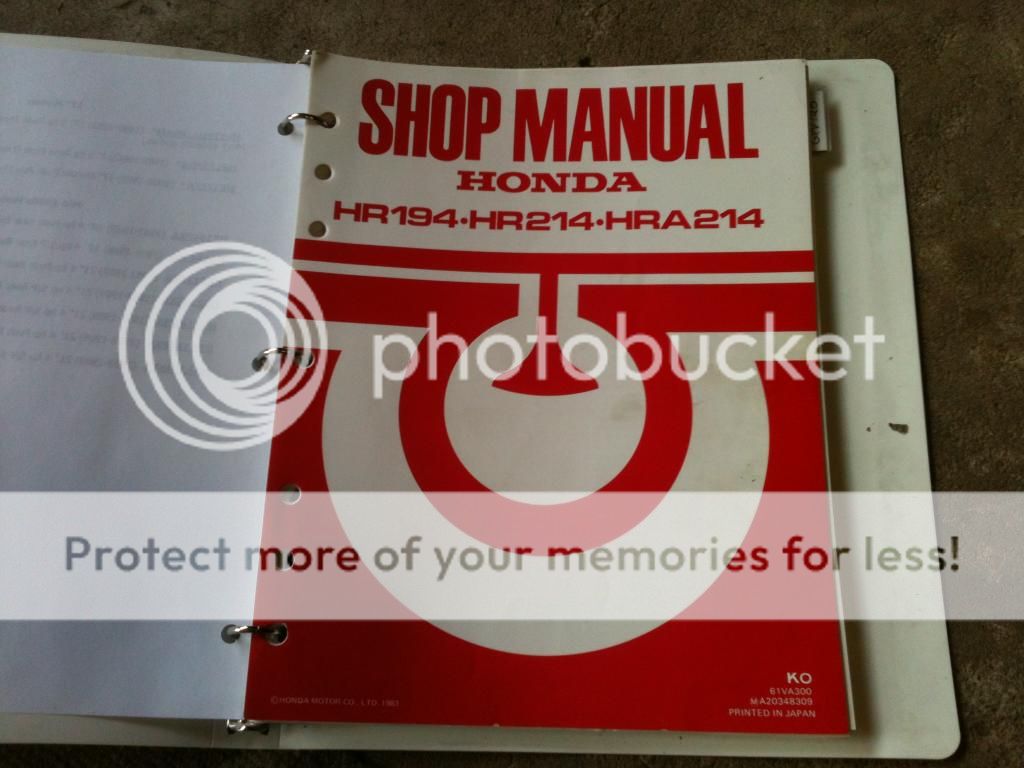
Oddly enough, there is a difference in the recommended settings between the manual for the mower, and the manual specific to the engine. I use the specs in the manual for the mower, which is .003 in. for the intake, and .005 in. for the exhaust.
If they need to be adjusted, use a 14mm wrench on the pivot nut and a 10mm socket on the lock nut. You might have to do this a couple of times, or more because it always seems to change when tightening the lock nut back up.

Then put your new valve cover gasket in place and the valve cover with just the bottom two bolts. The top two go on later when you put the shroud back on.
At this point I put the flywheel back on. Check the woodruff key, in fact, you might just want to go ahead an use a new one. Line the key way on the flywheel up and drop it into place. I use a very fancy tool at this point, it's called a compression tool, and it amounts to a length of rope. I turn the flywheel to get the piston at the bottom of it's stroke, insert a length of the rope through the spark plug hole and it serves to hold the crankshaft in place while I tighten the flywheel nut. As you tighten the nut, the piston compresses the rope until it holds the crankshaft from turning, then you can tighten the nut to specification.
Put the plastic cooling fan and the starter pulley in place on top of the flywheel, screw on the nut and tighten it to 50.6 to 57.9 ft-lb. Pull your rope out of the cylinder.
Reinstall the gas tank onto the back of the engine.
Now were ready to put the carb back on. Pay attention to the orientation of the gaskets and the thing called the insulator.
First gasket,

Insulator.

Second gasket.

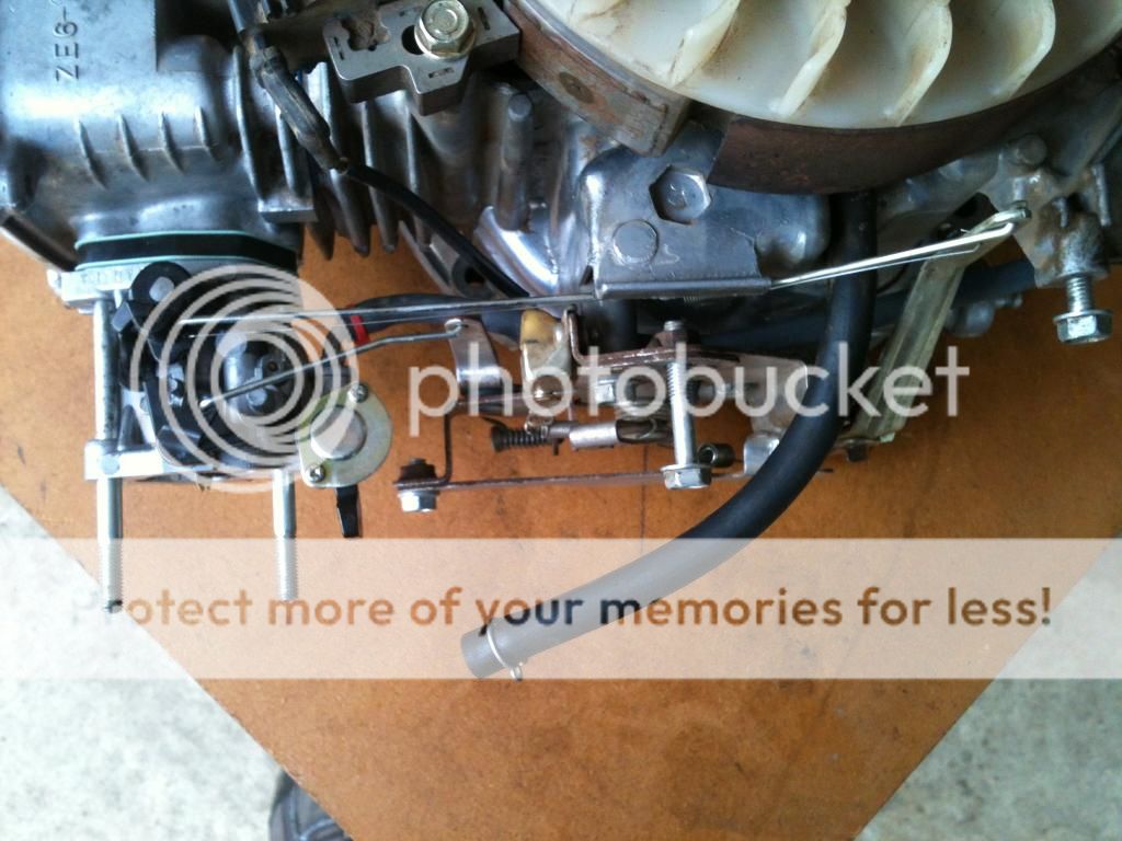
Now, slide the carb onto the bolts part way, put the choke rod into the choke lever on the carb. Push the fuel line from the gas tank through the little plastic holder on the back of the control. Finagle the other end of the choke rod into the hole it goes into on the control and reattach the control to the side of the engine. Reinstall the governor spring. There is a protective plate on the side of the control that you can take off, if you want, to make the installation of the governor spring easier.
Slip the end of the fuel line onto the carb. Put the end of the governor rod and the anti surge spring onto the governor arm. Line up the slotted hole in the throttle arm on the carb with the other end of the governor rod and slip the rod into place and then the end of the anti surge spring. Slide the carb up to the engine.

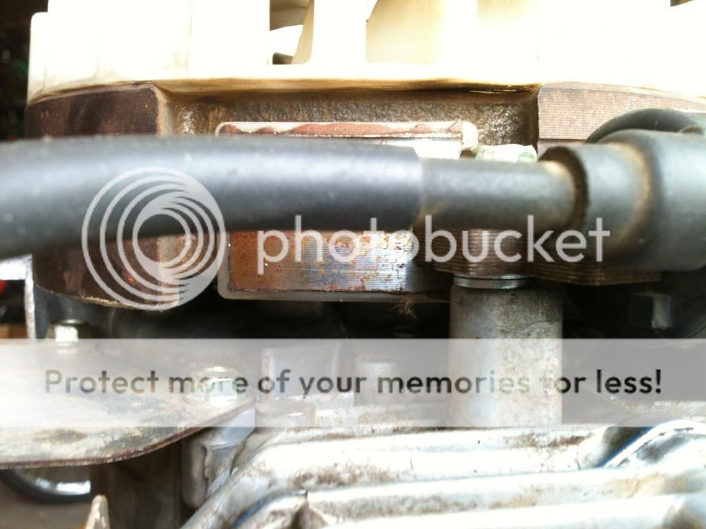
Slide the spacer on up to the carb. Again, take note of the placement of the holes.

Reinstall the coil. Your GXV120 might have a sort of odd looking coil with a big box like looking thing on top. If that coil ever fails, it can be replaced with part # 30500-ZG9-M02. I've used them on three different GXV120s, but, the arms on that coil aren't as wide and you have to use spacers or washers to raise it up a bit. Reconnect the stop switch wire to the coil.
We're almost there. New NGK BPR5ES spark plug. Next put the air box back on. Remember to attach the breather hose. Then the shroud. That darn fuel filler grommet is as hard to get back on as it is to get off. Slip the dip stick tube in place in the oil pan and bolt it in place up top. Go around and put the other bolts in, and take one final look in your parts bin to make sure you didn't forget anything. I hang a tag on the starter rope to remind me to put the oil in it after I've reinstalled the engine on the mower deck.
Take a deep breath, you're done.


 artyMan, that's neat! You got 'er all fixed up! I bet that engine can't wait to get back to work!